Tuesday, December 31, 2013

Primer and Adhesive Application


After blast cleaning and immediately before priming, dust and abrasive residue shall be removed with clean compressed air, clean soft bristle brushes or vacuuming. Priming of all surfaces shall be completed within four hours of blasting. 

Any surface which exceeds this time shall be re-blasted. The mixing, applying, drying and curing of the primers and adhesives shall be in accordance with the manufacturer's latest published instructions and the requirements specified therein. 

Primers and adhesives shall be thoroughly mixed until they are smooth and free of lumps. The minimum and maximum drying times between coats of the adhesive system and after the final coat of adhesive shall be in accordance with the manufacturer's latest published instruction and approved procedures. 

The adhesive system shall be recommended by or meet the approval of the rubber manufacturer. The primer coat of the adhesive system shall be applied to the substrate as soon as possible after completion of surface preparation and shall be completed before any visible rusting or surface contamination takes place.

The adhesive type, thickness of adhesive coats, compatibility with substrate, and the minimum and maximum drying times for the adhesives shall be as recommended by the rubber manufacturer. Minimum drying times for adhesives are dependent upon temperature and humidity. The adhesives also have a maximum drying time, after which the adhesive coat needs to be reapplied. The rubber manufacturer’s recommendation shall be followed in this regard.


The most important process parameters for achieving a high bonding strength are:
  • adhesive material
  • coating thickness
  • bonding temperature
  • processing time
  • chamber pressure
  • tool pressure
  • Homogenity

Adhesive bonding has the advantage of relatively low bonding temperature as well as the absence of electric voltage and current. Based on the fact that the wafers are not in direct contact, this procedure enables the use of different substrates, e.g. silicon, glass, metals and other semiconductor materials. A drawback is that small structures become wider during patterning which hampers the production of an accurate intermediate layer with tight dimension control.Further, the possibility of corrosion due to out-gassed products, thermal instability and penetration of moisture limits the reliability of the bonding process. Another disadvantage is the missing possibility of hermetically sealed encapsulation due to higher permeability of gas and water molecules while using organic adhesives.

The adhesives may be applied by brush, roller, or spray methods. Certain adhesives are degraded by exposure to direct sunlight. All surfaces shall be kept away from direct sunlight, and if an adhesive is exposed to sunlight, the adhesive manufacturer shall be consulted before proceeding. Surfaces shall be kept dry and examined for any presence of oxidation if the surfaces are inadvertently exposed to moisture. While we do primer and adhesive application must be watch out of homogenity of solution.


Tuesday, December 24, 2013

Surface Finish Inspection


One of the process involved in rubber lining is substrate inspectionsurface preparation and Surface Finish Inspection after blasting process. Before that, I want to introduce you all the standard for abrasive blasting cleaning.

Introduction to Industry Standards for Abrasive Blast Cleaning

•ASTM Abrasive Cleanliness Standards
•ASTM Compressed Air Cleanliness Standard
•ASTM Surface Profile/Roughness Measurement Standards
•ISO Dust Assessment Standard
•SSPC Abrasive Standards
•SSPC/NACE Surface Cleanliness Standards
•SSPC Surface Profile Measurement Frequency Standard (draft)

Here the all item that you should control when to use abrasive blasting:

· Quality of equipment and abrasive media
· Establishing process control to monitor quality
· Effect of ambient conditions on final abrasive blast cleaning
· Surface Cleanliness
· Surface profile and roughness
· Post-blast dust inspection

Quality of Abrasive Blast Cleaning Equipment

•Maintain Project Schedule (production)
ØCompressor Capacity
ØBlast Nozzle Wear
ØBlast Nozzle Air Pressure

•Maintain Quality
ØVerify Clean, Dry Compressed Air

•Compressor Capacity
ØRequirements based on multiple factors/conditions.
ØNo. of operators, nozzle sizes and required pressure are important considerations.
ØEquipment manufacturers publish charts for guidance.


•Monitoring Blast Nozzle Wear
ØAbrasive wears opening, reducing productivity
ØWear monitored using Pressure Blast Analyzer Gauge (nozzle orifice gauge)


 •Monitoring Blast Nozzle Pressure
ØReduction in nozzle pressure reduces productivity
ØPressure monitored using hypodermic needle pressure gauge


•Monitoring Compressed Air Cleanliness
ØOil or water in compressed air can contaminate abrasive and surfaces
Ø“Blotter Test” performed per ASTM D 4285
ØRequirement of SSPC Abrasive Blast Cleaning Standards


  In  This article I just will talk about Quality of Abrasive Blast Cleaning Equipment of Surface Finish Inspection. For the other item that you should control just see in the next article or just click on that name to get link. If you have any comment or hestation to ask just put yours in the coment box below.

Friday, December 20, 2013

Mechanism Corrosion


After you know the definition corrosion and localized corrostion,you will get the information about mechanism corrosion, just read the article below.

The picture above shows us why the metal to be corroded, just see the reaction process below. This series of steps tells us a lot about the mechanism corrosion.
(1) Ions are involved and need a medium to move in (usually water)
(2) Oxygen is involved and needs to be supplied
(3) The metal has to be willing to give up electrons to start the process
For those step happen the major component of steel, iron (Fe) at the surface of a component undergoes a number of simple changes. Firstly,
<Fe> → <Fen+> + n electrons
The iron atom can lose some electrons and become a positively charged ion. This allows it to bond to other groups of atoms that are negatively charged. We know that wet steel rusts to give a variant of iron oxide so the other half of the reaction must involve water (H2O) and oxygen (O2) something like this

{O2}+ 2 [H2O] + 4e- → 4[OH]
This makes sense as we have a negatively charged material that can combine with the iron and electrons, which are produced in the first reaction are used up.
2<Fe> + [O2]+ 2[H2O] → 2[Fe (OH)2]
Iron + Water with oxygen → Iron Hydroxide dissolved in it.
Oxygen dissolves quite readily in water and because there is usually an excess of it, reacts with the iron hydroxide.
4[Fe(OH)2]+ {O2}→ 2[H2O] + 2<Fe2O3.H2O>
Iron hydroxide + oxygen → water + Hydrated iron oxide (brown rust)
 
(4) A new material is formed and this may react again or could be protective of the original metal
(5) A series of simple steps are involved and a driving force is needed to achieve them, you can see the schematic process from the picture below.

The most important fact is that interfering with the steps allows the corrosion reaction to be stopped or slowed to a manageable rate in order to get persistence of the right life time of those material.

After you know the mechanism corrosion, so you will be ready to be the corrosion scientist or corrosion engineer, see the next writing how to differ the corrosion scientist and corrosion engineer


CORROSION ENGINEER


After you read Definition Corrosion, Mechanism Corrosion, and Localized Corrosion, it must be the basic knowledge in order to be Corrosion Scientist and Corrosion Engineer, but actually both are different. We must know what is the differences between them, just read this article.

 It has been said that the aim of science is “knowing why”, while technology deals with “knowing how”. One of the famous corrosion scientists, T.P. Hoar, considered the technologist as a person who utilizes his scientific knowledge to solve practical problems.

However, it is the situation and the technological problem that one is facing that decides the extent to which the practical solution can be based on scientific knowledge. 

In corrosion technology as Corrosion Engineering many problems are solved more or less by pure experience because the conditions are too complex to be described and explained theoretically. On the other hand, it is evident that great progress in corrosion technology can be obtained by the application of corrosion theory to practical problems to a much higher extent than what has been done traditionally.

This can be done i) in order to explain corrosion cases, to find the reasons and prevent new attacks, ii) in corrosion testing with the aim of materials selection, materials development etc., and in monitoring by electrochemical methods, iii) for the prediction of corrosion rates and localization, and iv) to improve methods for corrosion prevention in general, and to select and apply the methods more properly in specific situations.

This point of view is considered useful as a basis for corrosion education and it has been a guideline for teaching corrosion to mechanical and marine engineering. It starts with an article of the most important corrosion theory. Then we apply this theory as much as possible to practical corrosion problems.

Corrosion and corrosion protection is more interdisciplinary than most subjects in engineering. Consequently, mastery of corrosion means that it is necessary to have insight into 
physical chemistry and electrochemistryelectronics/electrical techniquesphysical metallurgymechanical properties of materials, fluid dynamicsselective design, joining technology, and the materials market situation.

These areas of knowledge constitute the foundation upon which corrosion technology is built. Since corrosion involves chemical change, the student must be familiar with principles of 
chemistry in order to understand corrosion reactions. Because corrosion processes are mostly electrochemical, an understanding of electrochemistry is also important. Furthermore, since structure and composition of a metal often determine corrosion behavior, the student should be familiar with the fundamentals of physical metallurgy as well.

The corrosion scientist studies corrosion mechanisms to improve (a) the understanding of the causes of corrosion and (b) the ways to prevent or at least minimize damage caused by corrosion.

The Corrosion Engineer, on the other hand, applies scientific knowledge to control corrosion. For example, the corrosion engineer uses 
cathodic protection on a large scale to prevent corrosion of buried pipelines, tests and develops new and better paints, prescribes proper dosage of corrosion inhibitors, or recommends the correct coating.


The corrosion scientist, in turn, develops better criteria of cathodic protection, outlines the molecular structure of chemical compounds that behave best as inhibitors, synthesizes corrosion - resistant alloys, and recommends heat treatment and compositional variations of alloys that will improve their performance. Both the scientific and engineering viewpoints supplement each other in the diagnosis of corrosion damage and in the prescription of remedies.

Those all the explanation of differences between corrosion scientist and Corrosion Engineer, I hope those make it clear in our mind set. If you have another opinion, just send comment in this blog, and let's discuss.

LOCALIZED CORROSION


After read Definition Corrosion and Main Groups of Corrosion which one of them is localized corrosion, here I explain about the type of localized corrosion and how to prevent it.

1. GALVANIC CORROSION

This can occur when two different metals are placed in contact with each other and is caused by the greater willingness of one to give up electrons than the other. Three special features of this mechanism need to operate for corrosion to occur:
Ø  The metals need to be in contact electrically
Ø  One metal needs to be significantly better at giving up electrons than the other
Ø  An additional path for ion and electron movement is necessary.

Prevention of this problem is based on ensuring that one or more of the three features do not exist. Break the electrical contact using plastic insulators or coatings between the metals. Select metals close together in the galvanic series. Prevent ion movement by coating the junction with an impermeable material, or ensure environment is dry and liquids cannot be trapped.

2. PITTING CORROSION

Pitting corrosion occurs in materials that have a protective film such as a corrosion product or when a coating breaks down. The exposed metal gives up electrons easily and the reaction initiates tiny pits with localized chemistry supporting rapid attack. Control can be ensured by:
Ø  Selecting a resistant material
Ø Ensuring a high enough flow velocity of fluids in contact with the material or frequent washing
Ø    Control of the chemistry of fluids and use of inhibitors
Ø  Use of a protective coating
Ø  Maintaining the material’s own protective film.
Note: Pits can be crack initiators in stressed components or those with residual stresses resulting from forming operations. This can lead to stress corrosion cracking, just see the Scheme of pitting corrosion below.


3. SELECTIVE ATTACK

This occurs in alloys such as brass when one component or phase is more susceptible to attack than another and corrodes preferentially leaving a porous material that crumbles. It is best avoided by selection of a resistant material but other means can be effective such as:
Ø  Coating the material
Ø  Reducing the aggressiveness of the environment
Ø  Use of cathodic protection

4. STRAY CURRENT CORROSION

When a direct current flows through an unintended path and the flow of electrons supports corrosion. This can occur in soils and flowing or stationary fluids. The most effective remedies involve controlling the current by:
Ø  Insulating the structure to be protected or the source of current
Ø  Earthing sources and/or the structure to be protected.
Ø  Applying cathodic protection
Ø  Using sacrificial targets.

5. MICROBIAL CORROSION

This general class covers the degradation of materials by bacteria, moulds and fungi or their by-products. It can occur by a range of actions such as:
a.       Attack of the metal or protective coating by acid by-products, sulphur, hydrogen sulphide or ammonia
b.      Direct interaction between the microbes and metal which sustains attack.
The microbiological corrosion is shown below with the schematic also.

Prevention can be achieved by:
Ø  Selection of resistant materials
Ø  Frequent cleaning
Ø  Control of chemistry of surrounding media and removal of nutrients
Ø  Use of biocides
Ø  Cathodic protection.

6. INTERGRANULAR CORROSION

This is preferential attack of the grain boundaries of the crystals that form the metal. It is caused by the physical and chemical differences between the centers and edges of the grain. It can be avoided by:
Ø  Selection of stabilized materials
Ø  Control of heat treatments and processing to avoid susceptible temperature range.
Here the schematic of intergranular corrosion, just see below


7. CONCENTRATION CELL CORROSION (CREVICE)

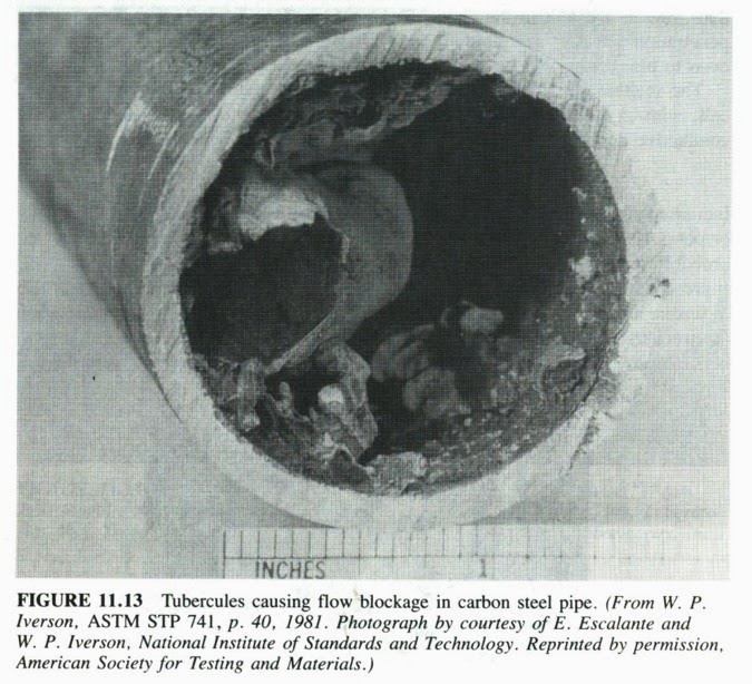
If two areas of a component in close proximity differ in the amount of reactive constituent available the reaction in one of the areas is speeded up. An example of this is crevice corrosion which occurs when oxygen cannot penetrate a crevice and a differential aeration cell is set up. Corrosion occurs rapidly in the area with less oxygen. Just see the example of crevice corrosion of gasket below and the schematic phase of it.


The potential for crevice corrosion can be reduced by:
Ø  Avoiding sharp corners and designing out stagnant areas
Ø  Use of sealants
Ø  Use welds instead of bolts or rivets
Ø  Selection of resistant materials


8. THERMOGALVANIC CORROSION

Temperature changes can alter the corrosion rate of a material and a good rule of thumb is that 10
oC rise doubles the corrosion rate. If one part of component is hotter than another the difference in the corrosion rate is accentuated by the thermal gradient and local attack occurs in a zone between the maximum and minimum temperatures. The best method of prevention is to design out the thermal gradient or supply a coolant to even out the difference.

9. CORROSION CAUSED BY COMBINED ACTION

This is corrosion accelerated by the action of fluid flow sometimes with the added pressure of abrasive particles in the stream. The protective layers and corrosion products of the metal are continually removed exposing fresh metal to corrosion. Prevention can be achieved by:
Ø  Reducing the flow rate and turbulence
Ø  Use of replaceable or robust linings in susceptible areas
Ø  Avoiding sudden changes of direction
Ø  Streamlining or avoiding obstructions to the flow

10. CORROSION FATIGUE

The combined action of cyclic stresses and a corrosive environment reduce the life of components below that expected by the action of fatigue alone. This can be reduced or prevented by;
Ø  Coating the material
Ø  Good design that reduces stress concentration
Ø  Avoiding sudden changes of section
Ø  Removing or isolating sources of cyclic stress

11. FRETTING CORROSION

Relative motion between two surfaces in contact by a stick-slip action causing breakdown of protective films or welding of the contact areas allowing other corrosion mechanisms to operate. Prevention is possible by:
Ø  Designing out vibrations
Ø  Lubrication of metal surfaces
Ø  Increasing the load between the surfaces to stop the motion
Ø  Surface treatments to reduce wear and increase friction coefficient.

12. STRESS CORROSION CRACKING

The combined action of a static tensile stress and corrosion which forms cracks and eventually catastrophic failure of the component. This is specific to a metal material paired with a specific environment. 


Prevention can be achieved by:
Ø  Reducing the overall stress level and designing out stress concentrations
Ø  Selection of a suitable material not susceptible to the environment
Ø  Design to minimise thermal and residual stresses
Ø  Developing compressive stresses in the surface the material
Ø  Use of a suitable protective coating

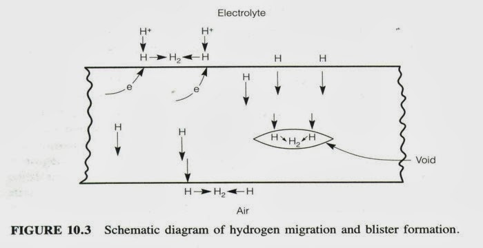
13 HYDROGEN DAMAGE

A surprising fact is that hydrogen atoms are very small and hydrogen ions even smaller and
can penetrate most metals. Hydrogen, by various mechanisms, embrittles a metal especially in areas of high hardness causing blistering or cracking especially in the presence of tensile stresses. 


This problem can be prevented by:
Ø  Using a resistant or hydrogen free material
Ø  Avoiding sources of hydrogen such as cathodic protection, pickling processes and certain welding 
     processes
Ø  Removal of hydrogen in the metal by baking.

After we know about localized corrosion, then we will go to the profession of corrosion namely corrosion engineer that you will see in the next article.


Add Button Share

Alexa Page Rank

bidvertiser